Canard Wing Construction for my IBIS homebuilt aircraft
A Canard wing for my RJ.03 IBIS
|
The latest news is always published at the top of this page.
If this is your first time around here, perhaps you'd better start to read from the bottom of this page.... :)
Shaping the foam
Today I have been shaping the foam that fills the wingtip and the space in between rib 4 and the new rib 5. This new rib #5 is part of the canard wing tip modification that JC makes available on request.
Even when wearing a dusk mask: I now remember why I didn't want to build a LongEze or some other slick GRP ship....
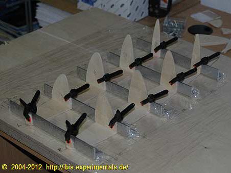
Glueing the perpendicular forming ribs
Currently the whole sheebang is glued together. Due to the close proximity of the forming ribs in the front and the 25x25mm size of the angles I used I had to glue the front forming ribs in multiple sessions.
Before glueing I touched up the mating surfaces with a bit of abrasive paper. After that I added the hardener to the resin and mixed it up thoroughly. I used this very liquid epoxy resin to give the mating surfaces a thin coat, the idea being that the thin resin increases surface penetration. After that, I added micro fibre to the remainder of the resin, to thicken it up and to make it more suitable for load carrying bonds. This thickened epoxy putty was then used to glue the perpendicular forming ribs to the no. 5 rib. A solid filler block at the trailing edge of the wing tips is still missing at this stage. As you can see, I have been liberal in applying epoxy, the fillets that were created this way are enough to support the former ribs until the empty space is filled with foam. B.t.w. in this stage (not yet cleaned up and no trailing edge filler block installed) each of them weighs exactly 90 grams (less than 3.2 oz).
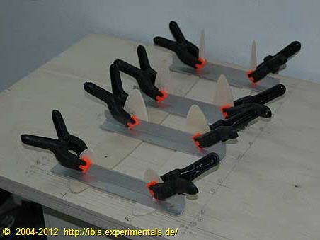
Dry fitting a last time
Final dry fit before glueing
All canard wing stuff, including the epoxy resin and hardener, has been put into my office. Here the temperature is more conducive to getting proper bonds. Everything has had two days to adapt to the higher temperatures. The parts that should go apart afterwards have been wrapped with thin polyethylene foil. The new no. 5 rib and five 25x25mm (1"x1") angles have been fixed to the assembly board so nothing is keeping me from finally assembling the first parts. Just one more dry fit of the perpendicular forming ribs to visually confirm that everything is setup right.
Canard tip - shape of things to come
First rough dry fit
To ensure that the former ribs are perpendicular to canard rib #5, I prepared a few angled pieces from a length of (non-aviation grade) scrap aluminium angles.
The angles are going to be wrapped with a sheet of polyethylene and are going to be fixed to the assembly board with three screws. I couldn't resist to do a dry run as the adjacent illustration shows.
The former ribs near the nose are very close to each other, there is not enough space for an aluminium angle for all of them at once. I'll start the glueing at the nose and do that section in multple runs. After that, the remainder of the former ribs can be glued in a single session.
Canard tip assembly board
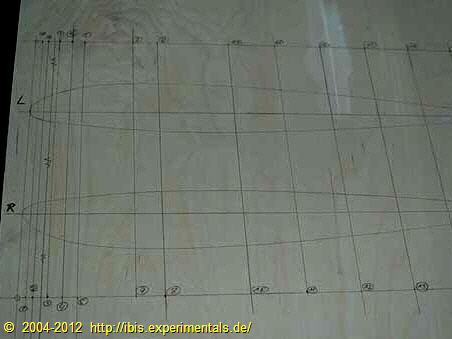
Canard wing tip assembly board with no.5 rib outline and stations marked for perpendicular forming ribs
Today I prepared a board to assemble the canard wing tips on. The plywood board is a 3 centimeter (1-1/5") thick job to assure a flat working surface and to minimise distortion when the epoxy sets. Of course it will be covered with a sheet of polyethylene so that the epoxy is not going to glue aircraft parts to the assembly board.
Currently my workshop is a bit too cold to do any epoxy glueing work, I'll move assembly board and canard wing tip parts to my office and do that part of the assembly there.
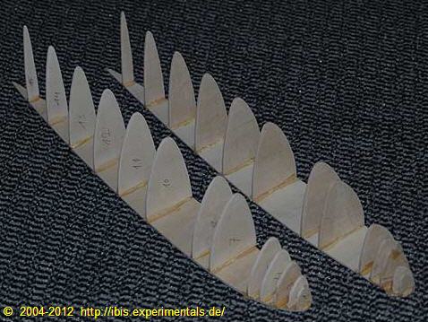
Canard wing tip parts completed
Former ribs cleaned up on a stationary disc sander
The new style canard wing tip parts are sized ready for assembly. I still need to peel the plywood parts apart and clean up the surface with a bit of coarse sandpaper, but this is a quick job.
Canard tip former ribs sawn out

Perpendicular former ribs cut out with a hacksaw
In this stage the canard tip form ribs are sawn out. From previous experience I learned that it is best to use sacrificial layers of plywood when you intend to use a rotary disc sander. The upper and lower plywood layers are sacrificial, the middle two layers are the ones that end up in the wing tips. Using sacrificial layers on top and on the bottom of the stack keeps the inner layers of plywood very clean.
I used a hacksaw with a cabinet maker's saw blade. These make very clean cuts and follow the curvature very nicely, so there's less to sand away with the stationary disc sander.
Shape of new canard wing tip
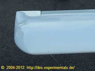
New style IBIS canard wing tip, as seen on F-PGLP
This picture shows what the new style canard wing tip looks like. This particular canard wing is the one on Henri Gallipot's very nice F-PGLP, but three more IBIS'es are currently flying with these new style canard wing tips: F-PBIS, F-PXPY and S5-MMA. Also, at least one builder (Christian Boutonnat) confirmed to me that he's ripping the original style wing tip apart to make place for the more recent version.
Original style canard wing tip
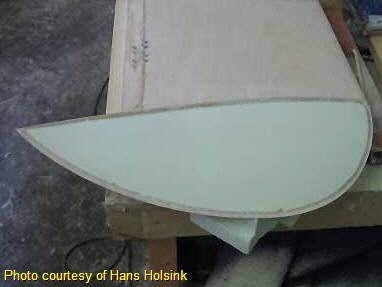
Original stye canard wing tip
This is what the original IBIS canard wing tip looks like, just as a comparison to the new style pictured in the paragraph above this one.
This canard wing tip is one that Hans Holsink built. You're looking at the bottom surface here. The emtpy 'hole' on the left is where the elevator is going to be mounted.
Extra ribs for the new style canard wing tip
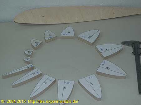
No.5 ribs for new style IBIS canard wing tip
These are the ribs I made with the template shown below. Square to these full ribs a number of small former ribs are glued that define the outline of the canard wing tip. The space in between these former ribs will be filled up with foam. After the foam is sanded down to the final tip shape, the surface gets a glass/epoxy covering.
Canard Wing Tip Template

IBIS canard wing rib templates
Canard wing tips on an IBIS come in two flavors: the original round one, and the more recent slightly triangular one. Since the designer claims that the more recent version produces less resistance, I opted to build that one. This new style wingtip needs an extra rib (no. 5 rib) and the template shown adjacent is what I used to create two extra ribs.
Canard wing assembly
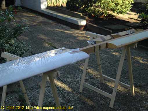
Canard wing assembly
In this stage the canard wing is assembled and is waiting for the wing tip construction and some more foam to fill up the interior space. I'm going to embed a single VOR/GS-antenna within the canard wing and have designed my own VOR/GS diplexer (antenna splitter) for this very purpose.
After completing these items, the canard wing is going to be covered with 0.8mm plywood, which is going to be glued to the foam and spars with a vacuum process.
Canard wingspar
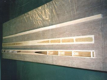
IBIS canard wing spar before closing
After glueing the spar caps and some internal reinforcments in way of the ribs, both the front- and backside get covered with a plywood shear web.
After completion, four mounting holes are drilled through the solid ash center piece. Through these four holes, the canard wing is bolted onto the fuselage front bulkhead.
The particular spar shown on the left was built by Mr. Tonny Tromp of Belgium. After Tonny decided to stop his project and build another type of aircraft, Hans Holsink (The Netherlands) decided to take over this spar.
The canard spar is shown just before glueing up the last shear web.
Canard spar center piece
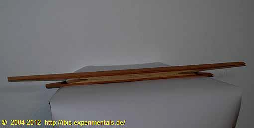
Center piece of IBIS canard wing spar
The picture shows what the canard spar center filler block looks like. The light colored wood is ash. This filler block is feathered into a upper and lower spar cap, both of which are not shown here.
Canard wing templates
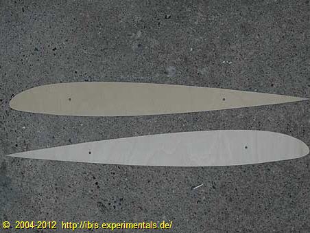
Canard wing templates
Producing the ribs for the canard wing is made much easier with these CNC water cut templates.
The template on the lower part of this picture is used later on to accurately locate both the index hole for the elevator hinges and for accurately locating the elevators themselves.
©2004-2012 IBIS RJ.03 "The French Canard" homebuilt aircraft project - canard wing
All rights reserved.