IBIS RJ.03 Landing Gear
The main landing gear dimensions are derived from the minimum required propeller clearance. The length of the nose gear is determined by the angle with which the fuselage needs to be set up. For grass strip operations, this angle is slightly larger than the normal one. |
The latest news is always published at the top of this page.
If this is your first time around here, perhaps you'd better start to read from the bottom of this (somewhat lengthy...) page.... :)
Nose wheel assembly
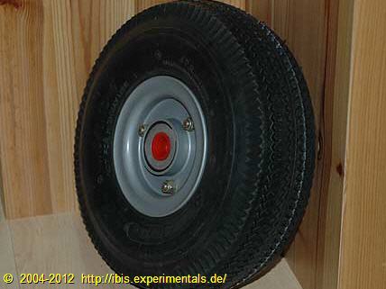
Groves 49-3A nose wheel assembly
This week the nose wheel assembly arrived. My brother Marcel needed some stuff for his Europa Classic Trigear (PH-MZW, ex. G-BWON). He was kind enough to let me piggy-back on his purchase order. Thanks again, Marcel!
The wheel is a Grove 49-3A, an aluminium CNC-machined job. The tire is a 4.10/3.50-4. As shown in the adjacent picture, the wheel assembly, tube and tire weigh 2.15 kg.
With these parts assembled, I can now start to take measurements to prepare for building the nose gear leg.
Final fitting of wheel assembly
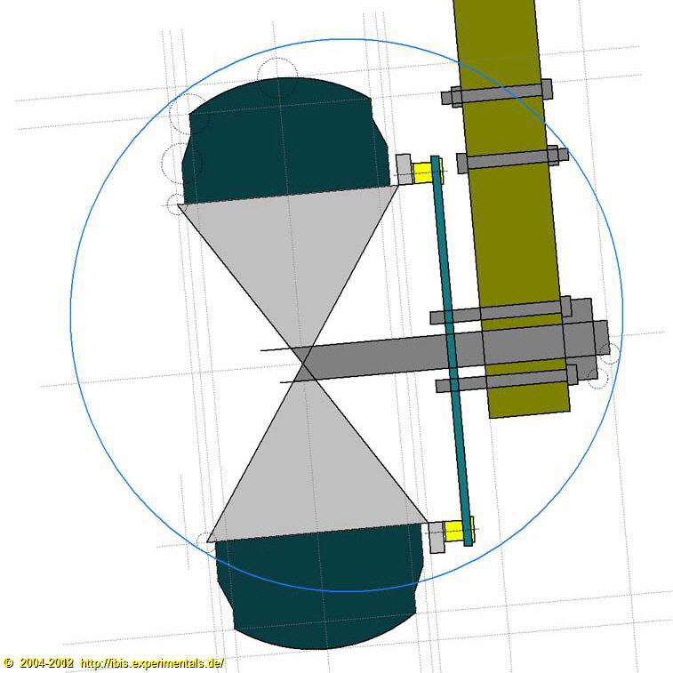
Geometry of wheel assembly
The next step was to drill the four hole bolt pattern into the flange of the brake house assembly. After that I could do a complete assembly for the first time, sort of a rehearsing for the final assembly. The fit was spot on. I didn't take any photo's this time, as these wouldn't look any different from the prior ones on this page.
I did take the opportunity to inflate the tire to 1.6 bar and to take exact measurements of the completed assembly. These measurements are needed when the time comes to develop a wheel spat design of my own. The bitmap to the right shows the drawing I created based on these measurements. Out of curiosity I tried to fit a minimal wheel spat shape around my gear geometry. In a quest to minimise wetted surface I initially tried to fit an ellipse around it. However, I soon found out that due to the distance my wheel assembly is mounted from the main gear leg, a circular cross section would be a better match. The blue circle shows my current best fit; it is one that satisfies the minimum separation constraints set forth in the builders manual. This cross section has a radius of 13.7 cm (appr. 5.4"). Based on this cross section I can now estimate that my wheel spat design is going to be some 70-75cm long...
Second wheel assembly fitted as well

The second gear assembly went on pretty much like the first one. The only difference being that the fit of the distance ring that keeps the brake assembly at the proper distance from the mounting flange is a bit too tight. No way to get it over the axle. The next step will be to adapt the reinforcing flanges to the brake assembly. Also I've prepared to cut the foam for the fairing that is glued on the aft (flat) part of the gear leg.
So, how much does it weigh? I put the assembly you see in this picture on a (non-calibrated) scale and it pegged at 17.2 kgs. There's still a few more things to add, stuff such as foam fairings with a glass/epoxy sheeting, some more hardware for the brakes and of course the wheel fairings. With a lot of attention to keeping things light - and a bit of luck - I'm confident that the main gear is ultimately going to weigh in at approximately 18.2 - 18.5 kgs all in all.
Testfitting of wheel & hydraulic brake assembly
Testfitting of the wheel and hydraulic brake assembly showed a couple of things:
- the hydraulic brake assembly requires some material to be removed from the rear lower side of the main gear leg as well as from the outer 4130 steel flange. JC tol d me that this modification is also required for those IBIS projects that use the wheel/brake assembly from MDO in Biarritz.
- the welded fillet on the modified axle necessitates a slight widening up of the central 16mm hole in one of the flanges and in a support ring as well. This is needed to fit both the axle flange and the brake housing flange tightly to the wheel leg.
- After these clean-ups, the wheel rim will be mounted 35mm from the gear leg, the inflated tire will have a bit less clearance.
Axle mated to main gear leg
Drilling the 16mm central hole that accomodates the axle was an interesting exercise. It's amazing how exact free-hand drilling can be. Intially I planned a contraption to be able to put the lot under a drill press, but after getting good results with the smaller M6 holes, my courage and self confidence were firm enough to also tacke the M16 likewise.
Fitting the flanges, axle hole not drilled yet
After drilling seven M6 holes though the main gear leg I couldn't resist doing a test fit. Of course I made a picture of this stage as well, showing the tangible results.
Drilling through some 35mm ash I was rather surprised about how hard that stuff is. Drilling was steady but rather slow.
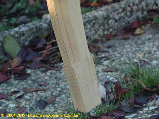
Preparing for drilling the main gear legs
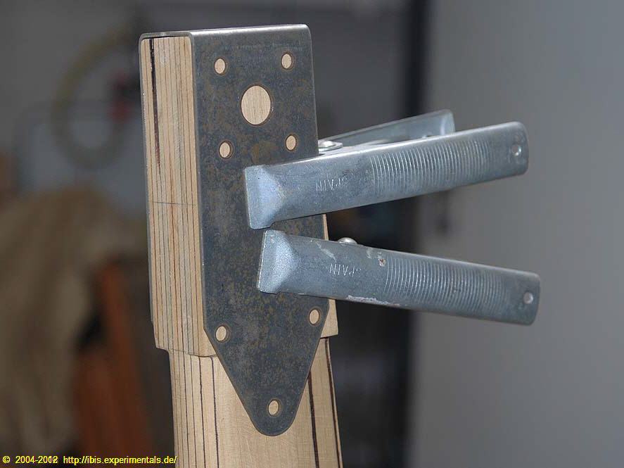
The bottom of the wheel leg wasn't quite perpendicular to the sides, so I used the rotary sander to get a nice planar and perpendicular bottom surface. After that, the outside edges were sanded down slightly to better fit into the radius of the bent 4130 steel flanges.
Then it was just a matter of measuring twice and drilling once. Well, almost so: following the advise of Hans Holsink I decided do the drilling in two parts, once from either side of the gear leg. Worked like charm.
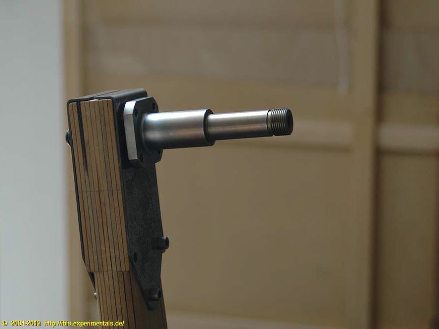
Axle modifications
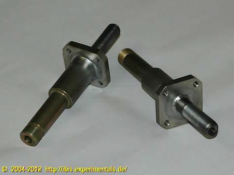
This is what the axles look like after Hans Holsink modified them for IBIS usage. The rectangular mounting flange was replaced with a (rounded off) square one, sporting the square bolt pattern that is specified by the IBIS construction plans. Hans also welded on the M16 extension that goes through the wooden gear leg. To top it off, he also drilled and tapped a hole in the end of the extension, so that I have a place to mount the wheel fairings. Thanks again, Hans!
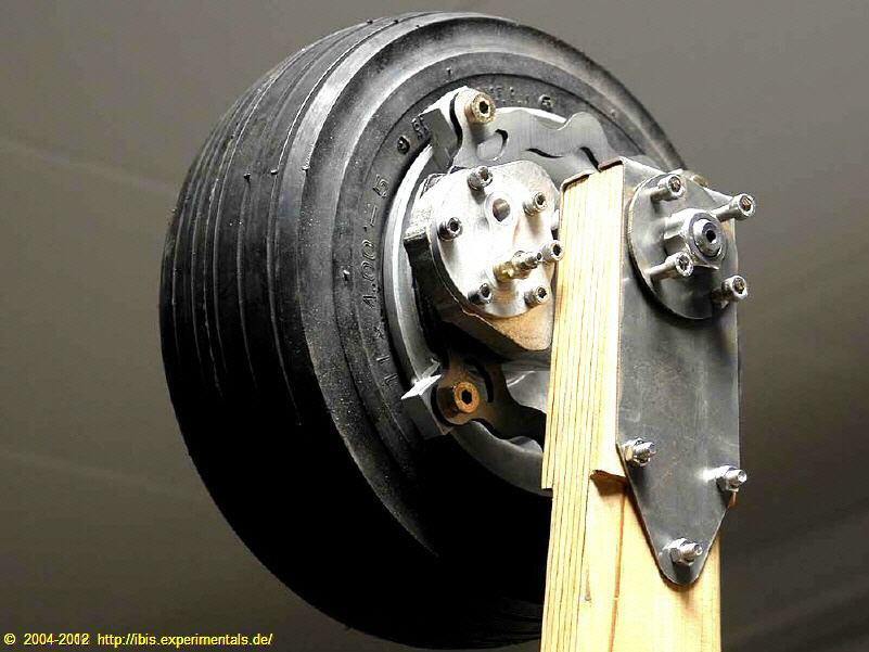
Wheel assembly
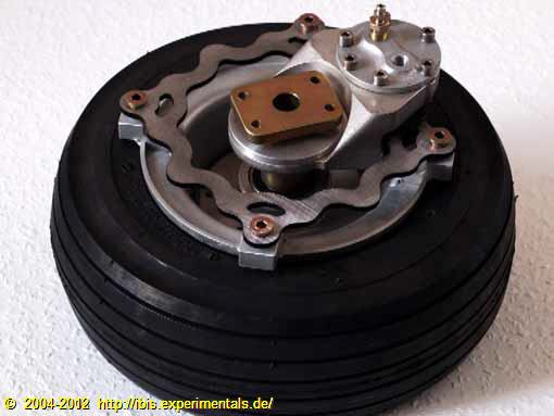
This is what it looks like when the whole sheebang is assembled (still with the unmodified axle here). The tire is an 11 x 4.00-5 job. This will make for some compact pressure recovering wheel spats, reducing drag to the max. The 11 x 4.00-5 tires might not be up to landing on very rough fields though. Then again, plenty of aircraft are operated from grass strips sporting 4.00's. Should I ever shorten the legs a bit and mount larger 5.00's, you know what happened...
Disk brake and braking pads
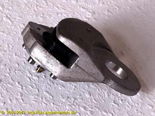
Here we see the disk brake assembly, the dark braking pads slid into the cavitiy and the hydraulic cylinder housing on top. After mounting the assembly on a gear leg, the attachement for the hydaulics is positioned behind the gear leg, which reduces chances of it being damaged by foreign objects during take-offs, landings and other ground operations.
Braking disk and parted rim
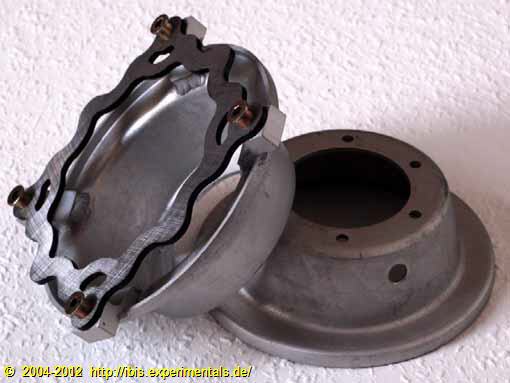
Parted Rim halves & braking disk
This is what a braking disk and the magnesium rim halves look like. Dividable rim halves are neccesery to be able to mount the small diameter tire.
The wheel rim halves, together with the hydraulic disk brake installation, are slid over the axle and bolted onto the hub shown above.
Main gear laminate lower ends
Port inside view of the main gear laminate
Like the middle section, the lower ends of the main gear laminate remain flat. This section houses the wheel & brake assembly. I've written something about mounting the maing gear wheel axes somewhere else on this site. Check it out, perhaps it contains food for thought. As always, comments that correct abberations in my thinking are welcome.
Axle and hub
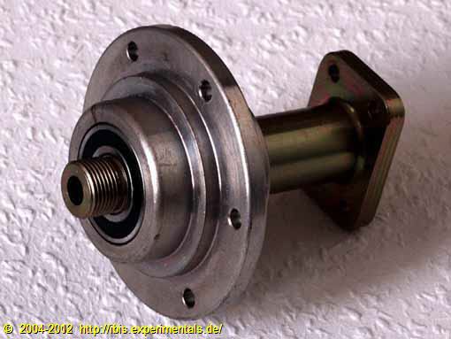
Main gear axle & Hub
The rectangular yellowish plated pad with the axle is a flange that is mounted on the outside of a gear leg. A bolt through the flange and gear leg tie the wheel- & gear leg assembly together. This pictures still shows the axle before Hans Holsink modified it for IBIS usage.
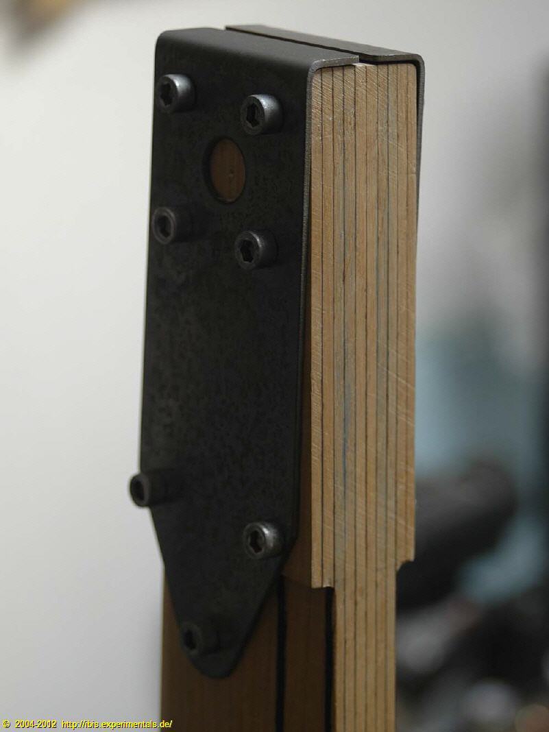
Main gear detail
Main gear detail, front side.
The front side of the main gear is rounded, which is clearly visible if you click on the picture to view a larger version of it. The flat section in the middle ends up inside the fuselage, so in this section the front is not rounded and the rear side doesn't sport a taper. On the large picture you can also discern the brown glue lines, which is what Aerodux glue looks like.
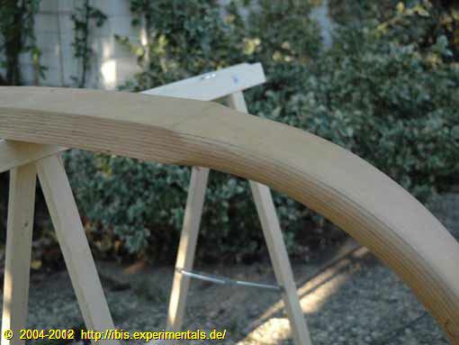
RJ.03 IBIS main gear ash laminate

This is what the main gear laminate looks like. It was glued with Aerodux.
Clicking on the adjacent picture will give you a better view of the details. This picture shows the aft side of the main gear laminate. The flat aft part will be used to add a glass covered foam strip which will help shape the arc's cross section into a symmetrical foil. The flat aft part will also be used to route the thin tubes for the hydraulic disc brakes.
Main gear mold

Main gear mold
The mold on which my main gear was laminated.
The main gear leg assembly is a single laminated arch, built up from 10 layers of 4.5mm ash. Total thickness of the middle section is 47mm. As these strips are appr. 14.5cm wide, there's plenty of opportunity to give it a nice drag-reducing streamlined form, as the plans specify. My main gear was laminated on the mold you see here.
The following two components are not part of the landing gear proper, but since they are related somewhat I parked them in here nonetheless, until I write a separate section that covers the braking system.
Braking pistons
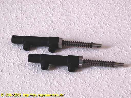
Braking pistons
The IBIS design sports a steerable nosewheel, so it's open to debate whether differential braking is all that useful. Since I took over these components from an abandoned project, I guess I'm going for differential breaking. That's how I was trained to handle aircraft on the ground, so for me it makes sense to equip my IBIS likewise. These cylinders are mounted behind the upper part of the front seat pedals.
Hydraulic fluid reservoir

Braking fluid reservoir
Since I'm going to install an hydraulic disk braking system, I need a reservoir to contain the reserve/expanded hydraulic fluid. This is it, small and simple. I've no idea where I'm going to mount this one just yet, but there's plenty of time to sort that out. The mounting location will be dictated by technical as well as service- and maintainance constraints.
©2004-2012 IBIS RJ.03 "The French Canard" homebuilt aircraft project
All rights reserved.