Metals and alloys for aircraft building
The original RJ.03 IBIS construction manual and plans were translated into English. Even then, not all material designations got translated as well, which is why I started to document the various designations for metal properties: |
Metal
The builders manual specifies steel in a cryptic (at least for me) French AFNOR designation, which turns out to be plain 'ol 4130 chrome moly steel. Three 18 x 36" sheets of various thickness are required to produce almost all things metal. For the nose gear, some steel tube is needed as well.
IBIS contol linkages are from 2024T4, both as tubes and some solid bars from which to machine a few parts.
AISI steel designation counterparts
| AISI | AFNOR | DIN | Werkstoff Nr (FRG) | Weld with |
| 4130 | 25 CD 4 | 25CrMo4 | 1.7218 | ER80S-D2 / Boehler DCMS-IG |
| 304 | X5CrNi18-10 | 1.4301 | ||
| 304L | Z 30 CN 18-10 | X2CrNi19-11 | 1.4306 | |
| 316 | X5CrNiMo17-12-2 | 1.4401 | ||
| 316L | X2CrNiMo17-12-2 | 1.4404 | ||
| 321H | X8CrNiTi18-10 | 1.4878 |
AISI aluminium designation counterparts
| AISI | AFNOR | DIN | Werkstoff Nr (FRG) | Remarks |
| 1100 | A 5 | Al99.5 | 3.0255 | pure aluminium, weldable |
| 2024 | A-U 4 G or A-U 4 G 1 | AlCuMg 2 | 3.1364 | not weldable |
| 6061 | AlMg 1 SiCu | 3.3211 | weldable | |
| 7075 | A-Z 5 GU | AlZnMgCu1.5 | 3.4365 | very high strength aluminium |
I mail-ordered my sheets of 4130 sheet metal and 2024-T3 aluminium tubes and other profiles/sections at Aircraft Spruce & Specialty Co. You might want to read up on my aircraft material purchasing experiences as reading this might save you money, especially so if you're based outside the USA.
4130 parts produced with CNC water cutting process
It's a very nice thing to be able to cooperate with builders that build the same design. As it happens, three other IBISes are in built in The Netherlands and - like me - each of these builders is a member of the NVAV. Hans Holsink is way ahead of the rest of us (EDIT: he's got his ship airborn...), which gives the other ones in the group opportunities to learn from his experiences.
Hans Holsink, a professional engineer by trade, prepared a set of CAD drawings to have his 4130 sheet metal cut with a CNC laser cutter. His experience and advise steered us clear of going that same route. We opted for the water cutting process instead.
Paul Raas, yet another professional engineer, prepared the CAD files for CNC water cutting. Also, he drew up CAD files for the templates needed for wing- and canard construction.
Bottom line: all members of the group had their 4130 sheet metal parts cut to 0.1mm (1/64") precision and saved a lot of time as well...
The next couple of paragraphs show some of the many parts produced with the CNC water cutting process.
Click on any of these thumbnails if you want to see a larger version.
Flaperon control bellcrank parts

Flaperon control bellcrank parts
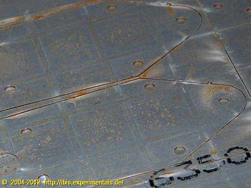
This is what the 4130 sheet looks like after the cutting process. In this particular example, the middle of the picture shows a number of parts that are needed to assemble flaperon control bellcranks.
Also note that each part is still connected to the 4130 sheet by means of a small 1 mm bridge. Each of the components was bent out quite easily. Fairing up the local shape after bending a part out went quick too. so now I can go ahead staight away with surface preparation, painting, etc.
Canard section templates
Canard wing templates
Although IBIS is primarily built from wood, the main wing and canard are filled with foam to stiffen up the outer plywood skin surfaces. This results in a potentially very smooth and stiff wing and canard surface. For this to happen, we need accurate templates to define the various core shapes. This picture shows the templates used for constructing the canard wing. The lower template is used to accurately mount the canard flap (elevator). You might be able to discern an index hole in the lower part of this template. This hole defines the exact location of the axis, around which the canard flap articulates.
Flap handle brackets

The two parts with the big holes are going to be the flap handle bracket. The flap handle will move between the two of them. These brackets still need to be notched, to be able to fix the flap setting at certain angles. The final arrangement will look somewhat like its counterpart on a Piper Cherokee.
Main gear axis reinforcements
Of course the main gear wheel axes are not going to be sticked through wood and carry the load just like that. My current thinking is to at least add a bushing, which I wrote about on this page. (See 'Axle & Hub')
A bushing is not the entire story though, it's just a way to prevent the local wood fibres from being crushed. Quite a bit more is needed to transfer the entire load up to the main gear. The parts you see on this picture are used on both sides of each main landing gear leg. The wheel axis is running through the central big hole. The smaller holes are used to mount a reinforcing ring. The upper holes (in the narrowing part) are used to further mount these reinforcements to the gear legs.
Since these reinforcement plates would entirely cover up any leg-internal bushing, these bushings could be made of cast fibre filled epoxy resin. The reinforcment plates block UV light, effectively protecting the cured epoxy.
Credits
Credit where credit is due: I'm very fortunate to know both Hans Holsink and Paul Raas, who created, edited and extended the files that made very accurate CNC cutting possible. A big 'thank you' to both of you!
©2004-2012 IBIS RJ.03 "The French Canard" homebuilt aircraft project
All rights reserved.